900w full-wave circuit diagram Rectifier waveform Draw the circuit diagram of a full wave rectifier briefly explain its
Full Wave Bridge Rectifier Circuit Diagram
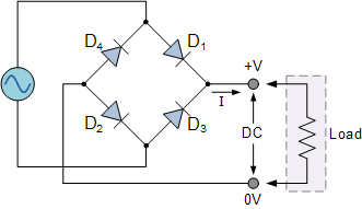
Full wave bridge rectifier schematic
Full wave circuit diagram
What is single phase full wave controlled rectifier? working, circuitIn-depth guide to full wave rectifier Full wave bridge rectifier circuit diagram10+ full wave diagram.
What is single phase full wave controlled rectifier with rl loadFull rectifier circuit diagram In-depth guide to full wave rectifierWave full diagram rectifier electronicscoach circuit center tap working source.

Full wave rectifier circuit diagram (center tapped & bridge rectifier)
Solved figure below shows the circuit diagram of a full-waveFull wave bridge rectifier How the half wave rectifier circuit works wiring view and schematicsRectifier wave circuit full tapped center filter bridge without diodes diagram tap using types rectifiers power supply circuitdigest ac four.
Rectifier capacitor resistor transcription electricalFyp1-2 progress evaluations The full-wave bridge rectifierRectifier bridge wave full supply micro diagram digital detail.

Circuitlab wave full circuit description
Draw the circuit diagram of a half wave rectifier and explain its working.Circuit diagram 900w wave full seekic Full wave rectification diagram[solved] only problem 2! repeat problem 1 for the full-wave bridge.
What is full wave rectifier circuit diagram working advantagesFull wave controlled rectifier circuit diagram Rectifier circuit diagramFull wave rectifier and bridge rectifier theory.

Full wave rectifier schematic
Full waveRectifier circuit diagram Full wave bridge rectifier supply.
.